Walt Stoneburner's Ramblings

Currating Chaos

Inventr.io Python Starter Kit, Lesson 1: Traffic Light Simulator

 •  • electronics, inventr.io

If you are here, you are likely trying to work your way through the Inventr.io Python Starter Kit as I was. This post is unaffiliated with Inventr.io, and just documents my experience working through the first lesson. It should contain everything you need to know, but wasn't covered in the course.

My purchasing decision was based on the expectation was that this would be an everything-included kit designed to teach absolutely beginner electronics, using Python.

It is assumed you've addressed setting up the Raspberry Pi Pico W in Lesson 0, which can itself be a small challenge for newbies on macOS, especially when the cable you need isn't included.

From what I can tell after this one lesson, it appears to be more about using Python than understanding the electronics that came with the kit. I'm hoping another kit serves as the intro, as the Inventr website does not make it clear what prerequisite knowledge is needed.

This post assumes you have pretty much you don't know what you're looking at or why the instructor is making the decisions they are.

What's Wrong With the Instructions

Surprisingly, how to set up the hardware is NOT DISCUSSED AT ALL in the lesson!

Worse, the breadboard diagram on the website, is different than the one shown in the video tutorial 11:19 (and lasts for less than a second on screen), and again doesn't match the completed project in the video tutorial at 20:52 either.

There are other nits:

  • The 'try' keyword is shown capitalized in the video at 07:19, which won't work.
  • The code for the LEDs in the video at 15:24 specifies pins 0, 1, and 2, which is wrong for the example given, though code on the website, which is different from the video, is correct with pins 16, 17, and 18.
  • The video shows the time library used, while the code on the website shows utime. (Both work.)

Additionally, because LEDs are diodes, they only work in one direction; this isn't covered. (Long leg is ground, btw.) And it isn't specified which resistor you should use, or why, or how to tell them apart.

Oh, and one of the resistor packs was mislabeled.

About the Circuit Breadboard

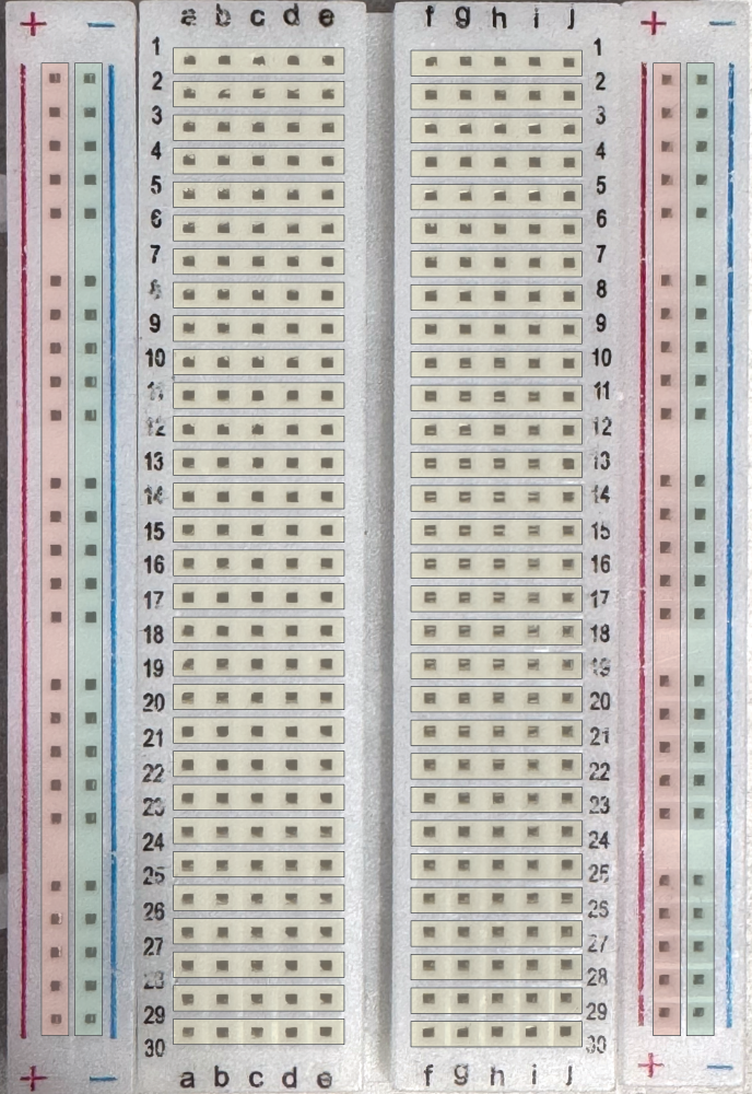
The circuit breadboard is structured so that it has two columns + and -, then ten columns labeled a to j, and another set of two columns + and -.

By convention, the red columns labeled + is where you connect the shared positive power, and the blue columns labeled - is where, by convention, you connect the shared ground (GND). The set on the left side is unrelated to the set on the right.

Each row, labeled 1 to 30 has a block of five pins connected, a to e, and then separately, f to j. If you want the whole row connected, you'll need to bridge the two sets.

The Circuit Breadboard internally connects certain rows and columns

Hardware Setup

It doesn't matter where the device is put, since all your wiring is relative to it. To access the pins, we need some space above and below the board. And, to give us some working room, we'll place it flush left for now.

Gently and evenly, with the MicroUSB facing the outside edge of the breadboard, place the Raspberry Pi Pico W onto the Breadboard at 30C–30H to C11–H11. Make sure no pins are bent, every one is aligned with, and smoothly going into, its corresponding hole.

Gently and evenly insert the Raspberry Pi Pico W into the Breadboard at 30C to H11

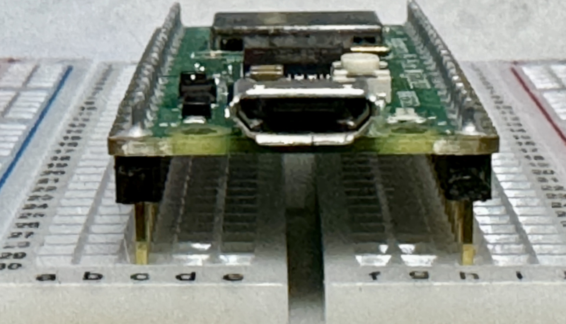
Then, gently depress it on each side — you may need to rock it — to get it to sit completely flush with the breadboard. It should go smoothly, do not force it.

You can then plug in the MicroUSB controller into the Raspberry Pi Pico W, and then into your computer, where presumably you are running the Thonny IDE, and have the MicroPython (Raspberry Pi Pico) - Board in FS mode selected in the IDE its bottom right.

Understanding the Pin Outs

The Raspberry Pi Pico W has forty pins. In the diagram below the start with 1 at the bottom left, increment to the right, then at pin 20 (far bottom right), the numbering continues counter-clockwise at the far top right, pin 21, and works right to left over to pin 40 at the top left.

Raspberry Pi Pico W mounted on the Circuit Breadboard

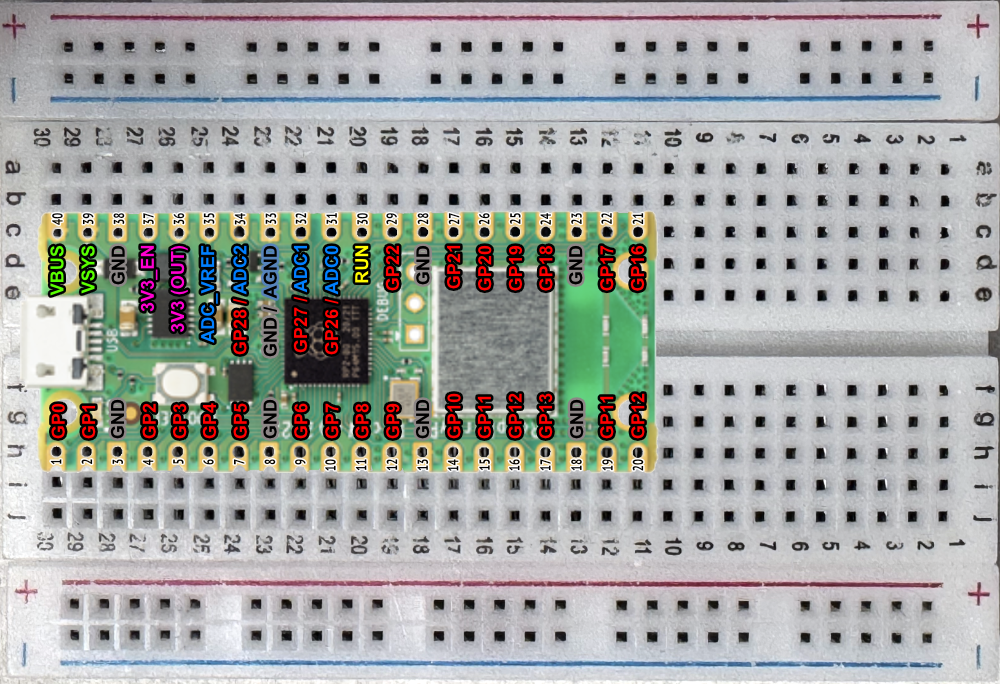
The General Purpose I/O (GPIO, or GPnn for short) represent digital pins that either assert voltage or not.

Note that the GPIO numbers to not match the physical pin numbers; rather, you get a few GPIO, then a ground (GND), then a few more, and another GND, etc.

It is these GPIO numbers that you use with code like:

1
led_at_gpio16 = machine.Pin(16, machine.Pin.OUT)  # GP16 is physical pin 21 on this device

More on this later. The GPIO numbers in red are the the ones you'll be concerned about when programming, and the row (a-e) or (f-j) will be where you want to be putting your wires to access them.

Power

If we look the diagram (see the purple labels on pins 36 and 37) the power pins are labeled as 3V3, which is shorthand for 3.3 Volts.

The GPIO pins will also be asserting this, when the pin is turned on.

1
some_led_set_by_machine_dot_Pin.value(True)  # True = on, False = off

All of the ground pins (see the grey entries) are labeled 'GND'. Also, if you look very closely at the Raspberry Pi Pico W circuit board, you'll see that the GND pins are square, the other are round.

NOTE: Don't connect a positive voltage directly to ground, or you'll cause an electrical short circuit.

About the LEDs

If you look at an LED, it has one wire shorter than the other. That short wire must be the one going to ground (GND). If the LED is turned around the other way, because it's a diode, it won't work.

Fun fact: Red and Orange LEDs take about 0.005 Amps; the other colors take about 0.010 Amps.

The power supply minus the LED forward drop voltages is equal to Amperage time Resistance, or I*R as you learned in school.

This means that solving V=IR for R, yielding the equation V/I=R, gives us our resistor value in Ohms.

Voltage / Amperage = Minimum Resistance Needed in Ohms

We know all the values...

3.3 Volts / 0.005 Amps = 660 Ohms (Ω) for Red and Orange LEDS.

3.3 Volts / 0.010 Amps = 330 Ohms (Ω) for other colors.

This means any resistor greater than 660 Ohms protects our Red LED, and any greater than 330 Ohms protects the other colors.

By rough hand waving, anything over 1000 Ohms is safe.
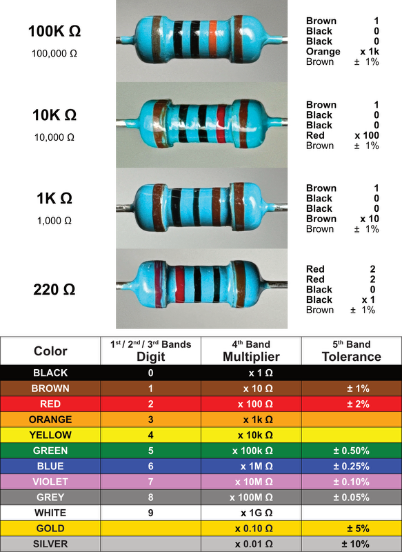
Resistors

Carefully look at the packaging, we've been given 1K, 10K, 100K, and 220K resistors. How do we tell them apart? Two ways.

One, by the color bands, assuming your eyes can see the color and detail. If I'm being honest, I had use a stand with alligator clips to hold them steady under a portable white lite desk lamp, and the iPhone Camera+: Pro Camera & Editor app in macro mode using steady shot.

The trick is telling which way to orient the resistor in order to read it right to left. And frankly, unless it's obvious, that brings us to method two.

Two, use a resistance meter. You can find simple ones for $10 or so, and there's some really nice ones by Klein Tools and you can go all out with Fluke.

Just measure it and be sure. I used a Klein Tools MM420.

Resistor Colors

Important Note

One of the resistor packages was mislabeled "220K" (that's 220,000 Ω) when it should have been 220 Ω. (Yours might be fine.)

Given that 220 Ω is less than the calculated 660Ω, 330Ω, and 1000 Ω numbers, it looks like we shouldn't use that set with the LEDs, just to be safe.

It's always a good idea to double check the resistors value with a multimeter rather than trusting hand notes on them.

About the Wires

You'll get a set of wires that look like a ribbon cable in a careful color arrangement. Trying to use them like that just doesn't work.

Turns out you can, and should, separate the wires like you would extract individual Twizzlers.
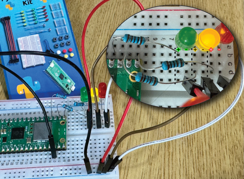
A Solution

I put the LEDs in column A, with the short legs consistently on odd rows, so I could easily know which leg needs to go to ground.

  • Red LED in 1A-2A (1A got the short leg, for ground)
  • Yellow LED in 3A-4A (3A got the short leg, for ground)
  • Green LED in 5A-6A (5A got the short leg, for ground)

Then, simply because they close to that side of the board, I used GP16 (to Red's 2A), GP17 (to Yellow's 4A), and GP18 (to Green's 6A), which supply power when those pins are turned on.

Since each LED needs a resistor, I used a 1K Ω resistor as a wire for each.

GP16 is C11, and row A11 to E11 are all connected, but some holes are covered up by the Raspberry Pi Pico W, leaving only A11 and B11 free (either will work, I used B11) and used a 1K Ω resistor to bridge to row 2 (that has the longer leg of the Red LED) picking 2D, just not to fatigue the resistor's wire.

GP17 is C12, using a 1K Ω resistor in similar manner to go from B12 to D4 (Yellow's long leg). In what feels like a game of Twister, but with wires, I made sure no exposed wires touched &emdash; this is important.

Note that the next physical pin is GND (in C13). GPIO pins do not have to be next to each other or even sequential.

GP18 is C14, using a 1K Ω resistor in similar manner to go from B14 to B6 (Green's long leg) — things were getting cramped, so I went with a free spot in the row so that no wires touched.

Now each LED needs a ground (GND). We can use the one at physical pin 18 (H13), so any of F13 to J13 will work. Since only I13 and J13 are physically available, we'll connect that to the ground plane using a wire (any color, but I went with black) from our rainbow pack of wires, and connect it to a blue (-) backplane. I stuck the other end of the wire in the fifth hole down in the blue (-) column two to the right of J, but anywhere is fine.

Finally, we connect from that ground plane column to the short legs of each the LEDs, which by convention we put in odd rows. Tear off three more wires. I put mine in 1E to the first hole in the blue (-) column that is two to the right of J. Then the next wire in 3E and in the second hole down. Then the next wire in 5E and the third hole down.

Final Lesson 1 Working

It's a lot of hops, and you're free to figure out a more optimal path using less distance or fewer wires.

Getting the GPIO Right in the Code

Know how we used GP16, GP17, and GP18? That means we need to use 16, 17, and 18 in the code.

1
2
3
4
# Initialize GPIO pins for LEDs
red_led = machine.Pin(16, machine.Pin.OUT)
yellow_led = machine.Pin(17, machine.Pin.OUT)
green_led = machine.Pin(18, machine.Pin.OUT)

You can use any GPIO you wish, as long as you connect it to the long leg of the desired LED, and then change the Python code to reflect which GPIO number you used.

Moving Serial Ports

To assemble the project, I disconnected my Raspberry Pi Pico W from the computer &emdash; partly so I could see what I was doing, second I didn't want to work with it powered up and risk the chance of plugging something into the wrong hole (which I did several times) and cause a short circuit harming something.

Only after I was sure, did I plug the device back into the computer.

When I got back to the Thonny IDE, it had all kinds of red error messages in its shell window. The play button was greyed out. It complained the serial port didn't exist.

So, I went down to the bottom right and went to select MicroPython (Raspberry Pi Pico) - Board in FS mode again. Turns out, the id number associated with the virtual serial port changed.

The moment I re-selected the "new" serial port, the run button re-appeared, and I was able to run the project.

Modified Code

I wanted my "Traffic Light" to blink much faster, and I wanted some indication the Pi was still working (so I wanted its built-in LED to blink to).

1
2
3
4
5
6
7
8
9
10
11
12
13
14
15
16
17
18
19
20
21
22
23
24
25
26
27
28
29
30
31
32
33
34
35
36
import machine
import utime

# Initialize GPIO pins for LEDs
red_led = machine.Pin(16, machine.Pin.OUT)
yellow_led = machine.Pin(17, machine.Pin.OUT)
green_led = machine.Pin(18, machine.Pin.OUT)

led = machine.Pin('LED', machine.Pin.OUT)

# Function to turn all LEDs off
def all_off():
red_led.value(0)
yellow_led.value(0)
green_led.value(0)

# Main Loop
while True:
all_off() # Turn all LEDs off

led.value(True)
utime.sleep(0.5)
led.value(False)

red_led.value(1) # Turn red LED on
utime.sleep(.5) # Wait for 5 seconds

all_off() # Turn all LEDs off

yellow_led.value(1) # Turn yellow LED on
utime.sleep(.5) # Wait for 1 second

all_off() # Turn all LEDs off

green_led.value(1) # Turn green LED on
utime.sleep(.5) # Wait for 4 seconds

Wrapping Up

Do I think you should get the Inventr.io Python Starter Kit? Absolutely.

You'll need to grab a MicroUSB cable that does data (not charging-only). You might want a cheap multimeter as well for checking the resistors.

You'll need to understand how the breadboard is wired, the LED polarity orientation, the resistor values, that you're supposed to peel of wires as you need them, and locate the GPIO ports on your Raspberry Pi Pico W, and use those values with your code.

The office training material appears to give you an idea of what to do, but it is not a step-by-step follow along. Know that going in, you'll do fine.

If this helped you, consider sending a small donation my way. If you noticed any errors or omissions, please reach out.

Inventr.io Python Starter Kit, Lesson 0: Getting Started

 •  • electronics, inventr.io

If you are here, you are likely trying to work your way through the setup of your Inventr.io Python Starter Kit and its Lesson 0 – Getting Started with your Raspberry Pi Pico W (Firmware, Thonny IDE, and Blink).

You can get to Lesson 0 through either:

  • https://inventr.io/PythonStart
  • https://learn.inventr.io/courses/micropython-starter-course/

Course materials are located through either:

  • https://inventr.io/downloads
  • https://learn.inventr.io/resources/

This information is on the back of the card that came with the kit.


This post is unaffiliated with Inventr.io, and just documents my experience working through the setup procedure on an Apple MacBook Pro M2 Max running macOS Sonoma 14.4.1 in April of 2024, which did not go smoothly.

My purchasing decision was based on the expectation was that this would be an everything-included kit designed to teach absolutely beginner electronics, using Python. I may have erred in that decision.

The kit appears to be more about using Python than understanding the electronics that came with the kit, which I was hoping for. The Inventr website does not make it clear what prerequisite knowledge is expected.

If you are already setup, then hop over to Lesson 1 – Traffic Light Simulator, as you are likely about to run into issues as I did.


Unpacking

The first thing you'll notice is a box of parts, you'll want to pull out the Raspberry Pi Pico W out of its sealed grey static bag; the device is embedded into some white styrofoam to protect it (leave it in for now, as it has long exposed pins we don't want to bend).

You will also need a MicroUSB cord, which is strangely absent. If you need to buy one, you can get a USB-C to MicroUSB or a USB-A to MicroUSB from Amazon.

Do not plug the cord into the computer yet, just plug the MicroUSB end of the cord into the Raspberry Pi Pico W.

Download the Latest Firmware

I suggest grabbing a copy from: https://rpf.io/pico-w-firmware

This resulted in downloading a file called RPI_PICO_W-20240222-v1.22.2.uf2 on 2024-04-13.

Beware that Inventr.io's "[DOWNLOAD FIRMWARE]" link will likely obtain an older version.

Installing the Firmware on the Device

This is where it gets a little tricky, because you're going to need multiple hands.

Before plugging anything into your computer, press and keep held down the BOOTSELECT button (it is a white oval button on the top of the circuit board labeled BOOTSEL). As you do this, plug the other end of the USB cable into the computer.

In a moment, you'll see a volume mount (similar to a thumb drive) labeled RPI-RP2. At that point you can let go.

Open that mounted drive, you should see a file called INFO_UF2.TXT and likely one other. If things look sparse, you're in the right place.

Now, copy the downloaded .uf2 file over to it. (You might do this by drag'n'drop or via the command line.)

The moment the file completes, the device instantly reboots, and installs the new file.

This sudden and unexpected dismounting will likely make macOS report that the drive was improperly ejected; it's fine, as the device choose to disconnect. Further more, if you go back and remount the device again, you'll see the file is gone — it gets deleted after it's been installed.

Installing the Thonny IDE

You could download the Thonny IDE from https://thonny.org/, as of 2024-04-13 it is v4.1.4.

However, I didn't want a .pkg making system configurations, and as much as I love HomeBrew, sometimes it just isn't up to date.

Note, for this to work, I do have Python 3.12 installed, which I did with: brew install python@3.12

I went with making a Python virtual environment:

1
2
3
4
5
6
7
8
9
10
11
12
mkdir thonny              # Creates a directory to work in
cd thonny # Go to that directory

python3.12 -m venv env # Make a virtual environment called 'env'

source env/bin/activate # Activate the 'env' virtual environment
pip install --upgrade pip # Upgrade pip while we're here

python --version # Should report v3.12.0 or better
pip --version # Should report v24.0 or better

pip install thonny # Install the thonny IDE

In the future, you would just cd thonny and source env/bin/activate.

Starting Thonny IDE

Just start the IDE by typing its name at the command line:

1
thonny

I was immediately greeted by a language choice. I picked English (US), Standard for initial settings, then clicked Let's Go.

The next step, as shown in their YouTube Video at 03:25 involves going down to the bottom right and selecting MicroPython (Raspberry Pi Pico)...

Except non-Windows machines don't have COMx: ports, and I'm using macOS.

The choices presented looked incorrect, and I selected the closest thing and got an error as the IDE crashed, with this hit that it was having problems:

1
2
[MainThread] INFO    thonny.plugins.micropython.mp_front: Listing serial ports
[MainThread] INFO thonny.plugins.micropython.mp_front: Falling back to serial.tools.list_ports.comports

Troubleshooting

macOS has two USB to Serial port drivers: /dev/tty.usbmodem21401 and /dev/cu.usbmodem21301. Your suffix numbers may vary.

Side Note: The 'tty' devices were used for "call-in" devices, waiting for a Carrier Detect signal on the line before establishing a connection; the 'cu' devices were used for "call-up" to call out, and is suitable when making a connection rather than waiting for one (the Carrier Detect signal need not be present).

Knowing that, we can try to connect to the Raspberry Pi Pico W with the only USB serial port we have available at the moment.

1
screen /dev/cu.usbmodem21301 115200

The screen program can connect to a specified device at the specified baudrate, effectively providing an interactive console terminal to the Pi.

Immediately after connecting, pressing Return on our keyboard should drop us into a Python interpreter on the device!

1
2
3
4
5
6
7
8
9
10
11
12
13
14
15
16
17
18
19
Welcome to MicroPython!

For online docs please visit http://docs.micropython.org/

For access to the hardware use the 'machine' module. RP2 specific commands
are in the 'rp2' module.

Quick overview of some objects:
machine.Pin(pin) -- get a pin, eg machine.Pin(0)

... lots more stuff ...

Useful control commands:
CTRL-C -- interrupt a running program
CTRL-D -- on a blank line, do a soft reset of the board
CTRL-E -- on a blank line, enter paste mode

For further help on a specific object, type help(obj)
For a list of available modules, type help('modules')

To get out of screen requires pressing Control-A then the letter 'k'.

After I did this and restarted Thonny (by typing thonny at the command line), I was able to select MicroPython (Raspberry Pi Pico) - Board in FS mode @ /dev/cu.usbmodem21301 (your suffix numbers may vary).

If you end up seeing something like the following, then it worked:

1
2
MicroPython v1.22.2 on 2024-02-22; Raspberry Pi Pico W with RP2040
Type "help()" for more information.

Installing the picozero module

Now go to Tools / Manage packages..., enter picozero and click Search micropython-lib and PyPl.

There should be a button to install it. Do that.

Except, for me, this resulted in an error:

1
2
Could not fetch search results:
<urlopen error [SSL: CERTIFICATE_VERIFY_FAILED] certificate verify failed: unable to get local issuer certificate (_ssl.c:1000)>

Tried loading from package directly from the link on the screen, that also failed.

Workaround for picozero.py

Note: over at https://projects.raspberrypi.org/en/projects/get-started-pico-w/1, they have a nice 'Installing picozero offline' set of instructions for different scenarios.

Grabbing straight from the source, I went to https://github.com/RaspberryPiFoundation/picozero/blob/main/picozero/picozero.py, clicked Raw, and right-click Save Page As... picozero.py

Back in Thonny, go to View / Files, then navigate to where you saved picozero.py (likely your ~/Downloads directory), select that file, and right-click and choose "Upload to /" from the menu, which sends it to the root on the Raspberry Pi Pico W.

Note the view display is not a new dialog, so closing the window closes the app; rather, it is a tab in a side bar, that you can close.

Finally Some Python Code

In the editor, copy'n'paste this:

1
2
3
4
5
6
7
8
9
10
import machine
import time

led = machine.Pin('LED', machine.Pin.OUT)

while True:
led.value(True)
time.sleep(1)
led.value(False)
time.sleep(1)

You can press the green Run button, and the LED will start flashing on the device. Success.

NOTE: In the next lesson, the author silently switches modules from import time to import utime. He also switches from using Boolean values to numerical 1s and 0s.

NOTE TO INSTRUCTOR: This kind of inconsistency can really boggle a student who is trying to build upon prior knowledge.

PlayDate imageLoad() Issue

 •  • playdate, lua

Using Panic's PlayDate Simulator Version 2.3.1 (165008) and Nova v11.8 (Build 573039) on a macOS Sonoma 14.2.1 (23C71), following the Inside PlayDate v2.3.1 SDK documentation, Section 6.16 Display for playdate.display.loadImage(), with this source:

1
playdate.display.loadImage("images/foobar")

I get this error message:

1
2
3
4
main.lua:31: loaded file properties don't match framebuffer's
stack traceback:
[C]: in field 'loadImage'
main.lua:31: in function <main.lua:24>

Panic recognizes it is a known bug introduced in May 2021 while trying to make font stoarage more efficient.

Solution

An ugly work around -- don't do this -- is to pad the image out to 416x240 pixels.

The correct workaround, and possibly long term fix, is:

1
playdate.graphics.image.new("images/foobar"):draw(0,0)

The images is loaded with image.new as a Lua object, and the draw method is invoked with the upper left screen coordinates.

Unfortunately, this isn't as fast as decompressing the image right into the framebuffer.

Panic's PlayDate handheld gaming console

Listing User Logins

 •  • linux

There's a helpful little comand called last that will show the historical logins of your Linux system's users.

Turns out, there's some additional flags you can add that will make it show a lot nicer output:

last -a -F -w -x

This has the advantage of showing if you have different ways of accesing the system, like mosh, this is called out as well.

Additionally, there's another command that's useful called lastlog that shows each user on your system and the last time that account has authenticated (if they have at all).

lastlog

iOS Deleting Undeleteable Photos

 •  • solved, iOS, Phone, iPhone, Photos

For years I've had a problem with Apple's OS X iPhoto and macOS Photos.

At one point, I had imported my photos but didn't indicate I wanted them deleted after the fact, a choice that takes a safety-first stance.

However, this left me in a weird state. Apple would not Import those photos again to the same library because they already existed, and as such they could not be deleted on import. The Photos app provides little in the way of managing your devices.

For whatever reason, even the Photo app on iOS itself would refuse to delete the images. In fact, I could select them, delete them, the thumbnail would disappear, but then when I flipped to another app (or another view within Photos), when I came back the files were there.

An aside for an unsolved problem that a reader may have the answer to: I can do a Select All on the phone with a small number of photos are presented, but I can't figure out how to do it all the time when there's a large number (several thousand while looking at my library, not an album), although I can select and drag ...but with that many it can take minutes to select everything. Anyhow know how to do a Select All of the photos on iOS? Please write me.

As for the delete operation. It wasn't that they ended up in the trash and needed manual deletion or a 30 day wait. It simply didn't work. Sometimes nothing would happen, sometimes the icons would disappear, although refreshing the view they'd all come back.

It's worth noting, I don't sync my photos to iCloud, so they're not reappeaing that way either.

To recap, the only thing on my phone at this point in the problem are the already backed up photos that I want deleted, they are local to the device but they won't go away and I'm not factory resetting.

SOLVED

Connect the phone to the desktop via USB and use the Image Capture software. At the time of this writing, I'm using macOS Monterey v12.6.

When you select your iPhone, you'll get a list of images. Here's where things get weird — likely a bug in Apple's UI Framework.

If you select all the photos with Command-A (which happens instantly), and in my case I had about 8,300+, and delete them, Image Capture will show you them being deleted, but if you exit and get back in, they'll be back.

If, however, you select and delete them 400 – 500 hundred at a time, then the deletion seems to stick. This requires selecting and using Shift-Click with the mouse. The good news is the less photos you have in your library, the faster the deletion operation happens.

It's almost as if the UI will let you select as many as you want, but the code that traverses a sequence of selected items within a collection of things can only process less than a thousand. Any more than that and it fails the operation but still removes the item from the list.

Unable to Restore from Rescuezilla (LVM)

 •  • rescuezilla, howto

I ran into a problem using Rescuezilla when trying to restore a succesful clone image back on top of the drive it came from (using v2.3.1).

The error I got was "failed to shutdown Logical Volume Manager (LVM)" with the only additional qualification that umount had an error. Why or what to do next wasn't addressed.

In looking at a forum thread on the matter, it suggested that perhaps this error message wasn't correct due to a bug in Filezilla (though I was using a version beyond the one specificed with the known problem).

It wasn't clear how to 'shutdown the LVM' myself, or what that actually meant. LVM stands for Logical Volume Manager, which can pool devices, make resizable volumes, handle data encryption, taking snapshots, etc.

Here was my solution that worked for me.

What I suspect is going on is that the destination is actually a logical volume exposed by LVM, and so this management process is still likely happening at the time you're trying to do a restore.

Using GParted, repartition the destination drive, leaving the device unformatted, and then do the clone to restore.

Part of me twitches, because this is indeed a destructive operation (then again, so is doing a restore); the hope being if a restore won't start, you at least have the old contents around. Not by this method you won't. Unless you take an additional backup of the data you're about to stomp on.

pfSense Host Overrides are Not Resolving

 •  • solved, pfSense, firewall, dns

I use pfSense for a firewall, and more recently pfSense+ simply because that's what came on the new Netgate 5100.

pfSense also provides several DNS options: DNS Resolver (unbound), bind, and DNS Forwarder. I use the DNS Resolver.

One of the cool features is Host Overrides. This allows one to get pfSense to give back DNS responses that override the typical DNS response; that could be to block certain services, set up testing domains and hosts, or provide local DNS resolution for machines you don't want publically resolved.

For me, a few years ago this stopped working, and I sat on the problem until I had some significant time to dig into it. The full details are on Netgate's forum. This is worth the read if you are facing similar problems and wish to troubleshoot.

The symptoms were that dig and nslookup commands were working just fine for external hosts, but when I tried to look up any of my Host Overrides, I didn't get back an answer (instead, I got missing host or missing domain).

I had a Transparent Zone Type, DNSSEC enabled, and Forwarding Mode enabled (and being disabled didn't help either). Turns out, none of this mattered. Tests with the DNS Resolution Behavior to even ignore remote DNS servers didn't change the symptoms. Nothing on pfSense seemed to explain it, not ACLs, not other resolvers, not pfblocker, not other packages.

Even weirder was if I used ssh to get onto the pfSense box itself, doing the same DNS lookups there caused it to properly honor the Host Overrides. It was acting as if pfSense was ignoring Host Overrides for downstream devices. Acting, it turns out, was the key word.

The solution started to sort itself out when using pfSense's Diagnostic / Packet Capture against port 53. When I'd do digs against my Host Overrides, I'd see no traffic! When I'd do a dig against google, I'd see a response ...but not for google!

Something was performing DNS Over HTTPS. Several somethings, actually. Firewalla Gold was configured to do it, as were my browser settings; all for security reasons.

When DNS Over HTTPS is turned on, the DNS request is forward via HTTPS outside the network, where it's resolve externally — and not at pfSense's DNS Resolver, hence why the Host Override wasn't working and why there was no port traffic to pfSense's DNS.

The Solution was to simply turn off DNS Over HTTPS, and suddenly the DNS requests went to pfSense's Resolver, which happily answered the Host Overrides, and all was well.

The better approach appears to be DNS Over TLS and to let pfSense do it, not an upstream device.

Netgate SG-4860 Bricked

 •  • solved, pfSense, firewall, netgate

This afternoon while updating my Netgate SG-4860 pfSense firewall from version 2.5.2 to 2.6.0, a process that's seamless and takes mere moments to upgrade and reboot, the GUI web console reported that the firewall was not coming back from its soft reboot.

When I went to check on the firewall, it was off. That was highly unusual.

When I unplugged it and plugged it back in, the status light turned red, the web interface wouldn't load, and the device powered itself back off. I couldn't ssh nor ping the device.

At that point, I went to the USB serial console to figure out what was happening. Details of how to do this are readily available at Netgate's Website.

Typically, one grabs a Mini-USB to USB-A cable, be sure to get a real cable (it has a thick cord) and not one for charging devices (it has a thin cord), and a USB Bridge to UART driver. Here are several:

Some of the newer Netgate modles have UARTs that require the full UART capabilities. On a side note, many of these drivers take an unusually long time to install (so much so, you'll think they've hung) on Apple or Microsoft systems. Most modern Linux kernels come with a driver already, so nothing need be installed on that platform unless you are using a much older kernel.

At that point, when a powered up Netgate device is connected to your computer via the USB cable, a device called /dev/cu.SLAB_USBtoUART or /dev/cu.usbserial will appear. (The "cu" means "calling unit", such as the old days of connecting to a phone modem.) You'll want to connect to the serial port with the settings of N,8,1 and a default baudrate of 115200, using no hardware handshakes (RTS/CTS), nor software flow control (^S/^Q). While you could use minicom, it turns out that you can also use screen and specify the baudrate:

$ screen /dev/cu.usbserial 115200

You may have to press enter to wake the pfSense terminal console. And, if you're using screen Control-A d will disconnect.

In my case, I got nothing. No text console. The device was dead.

In reality, the device was bricked.

This reddit thread by pfn0nsense outlines the problem perfectly:

I have a SG-4860 that has been running great for 3+ years, but has recently turned into a brick. The status light is solid red on power up, but eventually just turns off. I am unable to see any output via the USB console port. As far as I can tell this happened out of the blue, not during a reboot or any sort of update or power cycle.

And, ProperToday8 had an answer no one likes to hear -- it's an honest-to-God known hardware problem.

You have fallen victim to the Intel Atom C2000 SoC flaw. Google it.

The Intel Atom C2000 bug has been killing products from a variety of different manufactures, at least since 2017.

Cisco explains it in a support advisory entitles Clock Signal Component Issue.

In some units, we have seen the clock signal component degrade over time. Although the Cisco products with this component are currently performing normally, we expect product failures to increase over the years, beginning after the unit has been in operation for approximately 18 months. Once the component has failed, the system will stop functioning, will not boot, and is not recoverable. This component is also used by other companies.

Other folks have been reporting it:

Netgate, aware of the issue, commits to repairing or replacing the unit if you're still under warranty. If you're not under warranty, you could be looking at a replacement cost upwards of $500 including a $75 diagnostic fee.

More than likely if you are leaning in that direction by being out of warranty, you might as well purchase a new unit. If you reach out to them, they may comp you an extra year on the replacement unit.

For those that are curious, I did try factory reseting the device, downloading the original firmware and attempting to install it via USB stick, but alas -- the device can't read its boot ROM to get that far.

So the "solution" is to decomission the device, plan on it never coming back, and replacing it with a newer, faster, better model. Netgate has many appliances.
pfSense recommends some too.

Should some brilliant electrical engineer out there happen to know how to take a screw driver and a soldering iron to the unit and correct the problem with some replacement component, please reach out to me. I don't intend on disposing the unit for a while. Extra bonus points if the unit can be repurposed to a general computer or the parts salvaged.

Strange Preference Files

 •  • MacOS

Ran into a mystery today. Inside my ~/Library/Preferences directory were two files that had short names, unidentifable, cryptic names that contained obscure Unicode.

$ cd ~/Library/Preferences
$ ls -l | tail -n 2  This shows two strange files
-rw-rw-r--@  1 root  admin     240 Oct 13  2020 …hgdlkf
-rw-rw-r--@  1 wls   staff     240 Dec 19  2020 …^?fiilh

When doing a search, this article seems to indicate that the hdglkf file was MAMP PRO's doing. I certainly hope that is not the case, I love those folks.

The files are 240 bytes each, containing binary. Maybe it's a license or some piece of saved state... but it certainly isn't following the Apple filenaming conventions for this directory.

A little closer inspection shows the filenames are really mangled. This is not discorruption, it's obfucation.

$ ls -1 *dlk* *iilh | od -a -t x1

Binary Characters in the Filenames

 .   .   .  h   g   d   l   k   f   .   .      
e2  80  a6  68  67  64  6c  6b  66  c2  a0

 .   .   .  del f   i   i   l   h
e2  80  a6  7f  66  69  69  6c  68

The Unicode e2 80 a6 (U+2026) is the HORIZONTAL ELLIPSIS. The Unicode c2 a0 (U+00A0) is the NO-BREAK SPACE.

The Finder has a problem showing these files.

With GNU bash, version 3.2.57(1)-release (x86_64-apple-darwin18), the only way I can even type these files is with wildcarding like this:

$ ls -l@e *hgdlkf* *fiilh

Due to trailing Unicode, this won't catch the first:

$ ls -1 *hgdlkf  # Remember, there's a hidden no-break space

The com.apple.FinderInfo 32, which appears in the directory listing makes the file(s) not visible from Finder. One fixes that with:

$ xattr -d com.apple.FinderInfo *fiilh

For now I've moved both files to a holding file outside of Preferences to assess the fall out.

For what it's worth, MAMP PRO still seems to start, acknowledge I'm registered, and shows all my resources.

Apple's Pages: Layout Break

 •  • Pages, Apple, solved

Let's say you're working in Apple's Pages and you really want to create a multi-column section of text inside some other block of text.

In other word processors, you'd insert a section break (without a page break), something with two or more columns, and then again a section break (without a page break). You're aiming for something like this:

Two Columns Embedded in Text using Pages

And while Apple's documentation for Pages implies it's possible, comparing the invisibles to the menu items, you'd find a glaring omission in the application's menu.

Layout Break Does Not Appear in the Meny

In fact, no where in the Pages User Guide for Mac does it tell you how to do that.

Back in the days of iWork, it used to be possible engage in a little dance where you'd insert a section break, twiddle columns, and then delete the part that caused the page break. It was ugly, but it worked. But not in Pages.

Solution

Say you have a column of text. Select a block in the middle of it. Then, making sure you're on the Layout Tab, change the Columns.

Select, Layout, and Columns

The trick is that you have to alter the column count while you have the content selected. If it's not selected, it won't work.